Pre fitted cable guide can now be discarded.
Cable gland installation procedure.
Installation should only be carried out by a competent person with relevant knowledge and skilled in the installation of cable glands.
If required fit shroud b push the cable through the diaphragm seal armour spigot.
Procedure cmp cable gland installation general requirements all works shall be carried out in accordance with the approved project specifications drawings diagrams schedules lists data specification sheet and relevant approved itp s and procedure with manufacturer s recommendation as required.
The cable gland cable cleat and accessories specialist call us today on 44 191 265 7411 coronavirus notice.
Gland preparation a strip cable to suit equipment as shown above and expose the armour braid i.
We are monitoring the situation with covid 19 have measures in place.
Installation instructions for cable gland type cx it is not necessary to dismantle the cable gland any further than illustrated below 1.
In accordance with the above the following guidelines will help ensure that the installation of cable glands ensures a safe and reliable connection.
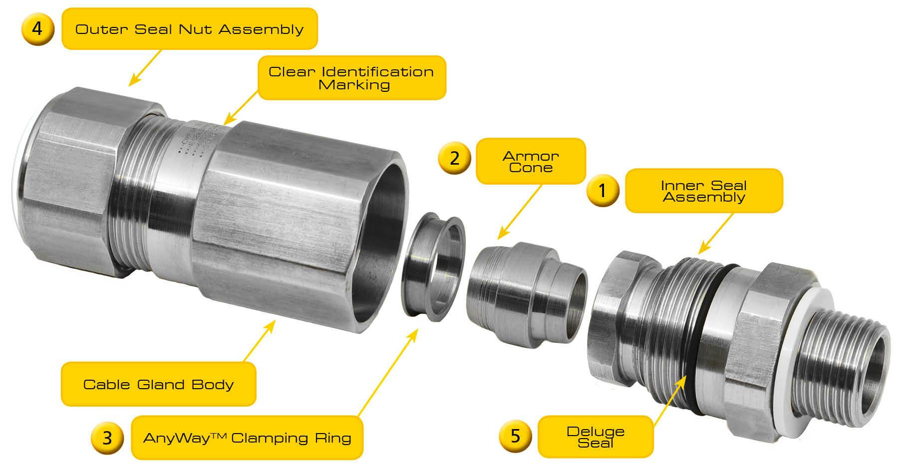
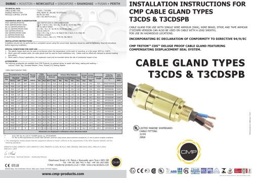
Installation of cable gland type t3cds installation instructions 1 select the correct cable gland size using physical dimensions of the cable cross referenced against the selection table opposite.
The cable glands may not be modified by the customer.
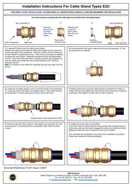
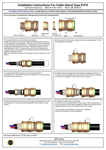
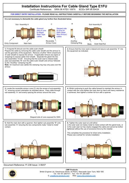
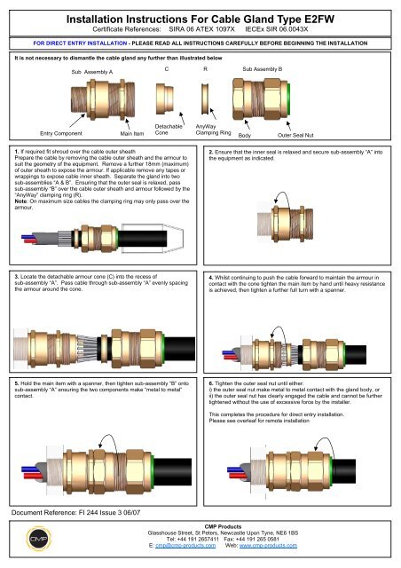
If required fit shroud over the cable outer sheath prepare the cable by removing the cable outer sheath and the armour to suit the geometry of the equipment.
Click here for more information.
M20 x 1 5 and m25 x 1 5.
Failure to comply with the instructions below will render the atex iecex certifications invalid.
Cable gland installation guide installation installation of the cable glands must be completed by a skilled technician or engineer.
I 20mm for cable gland sizes os to c i 25mm for cable gland sizes c2 to f ii to suit equipment.
Training can be facilitated or provided by cmp products.
Fi 242 issue 3 06 07 it is not necessary to dismantle the cable gland any further than illustrated below 1.
Remove a further 18mm maximum.